
Guided Cylinders
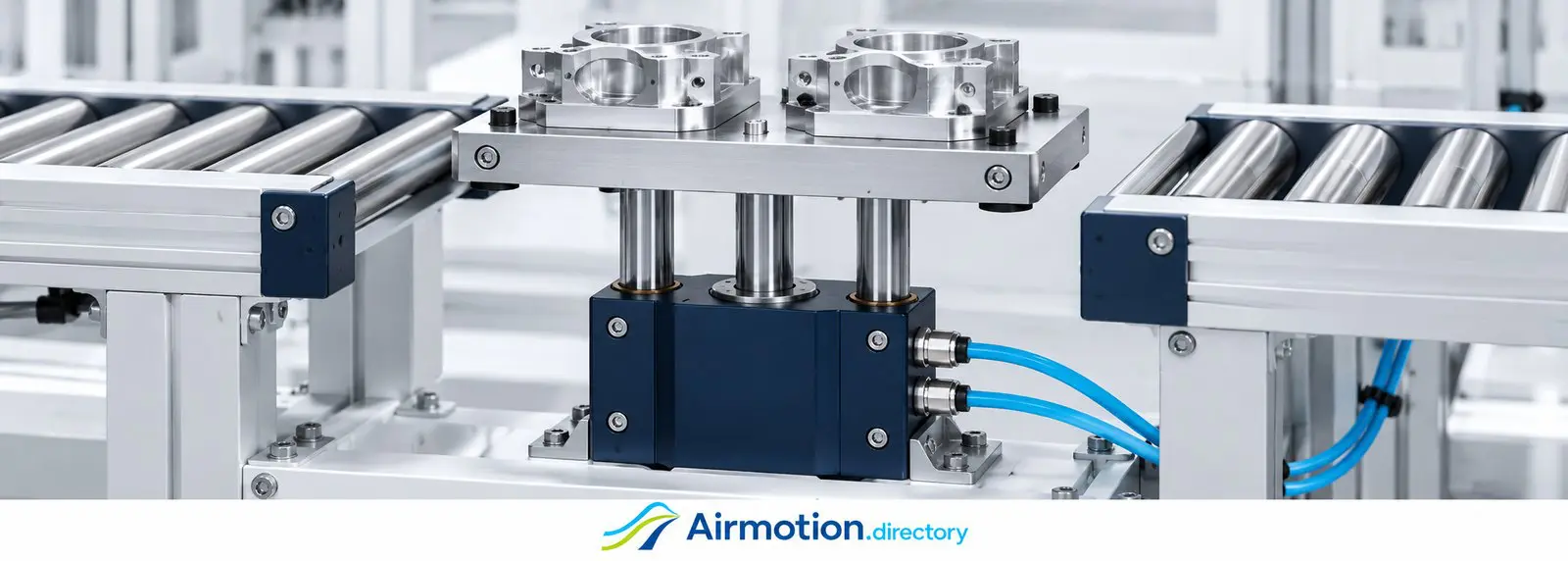
Move the load. Keep it aligned.
A guided pneumatic cylinder combines air-powered linear motion with a guide arrangement that resists rotation and supports specified side loads and turning moments. It is useful when a platform, pusher or tool must retain its orientation as it moves.
What do the guides do?
Compressed air produces thrust in the cylinder. Guide shafts and bearings support the moving plate and help control rotation and deflection under load. The cylinder supplies the movement; the guide arrangement addresses how the attached load is supported. Designs may integrate these parts in one body or combine a cylinder with a separate guide unit.
A cylinder’s push-force rating does not establish its ability to carry an offset load. The selected guide still has limits for load, moment, stroke and operating conditions. Compare this category with standard pneumatic cylinders and compact cylinders when deciding whether additional guidance is needed.
Three practical applications
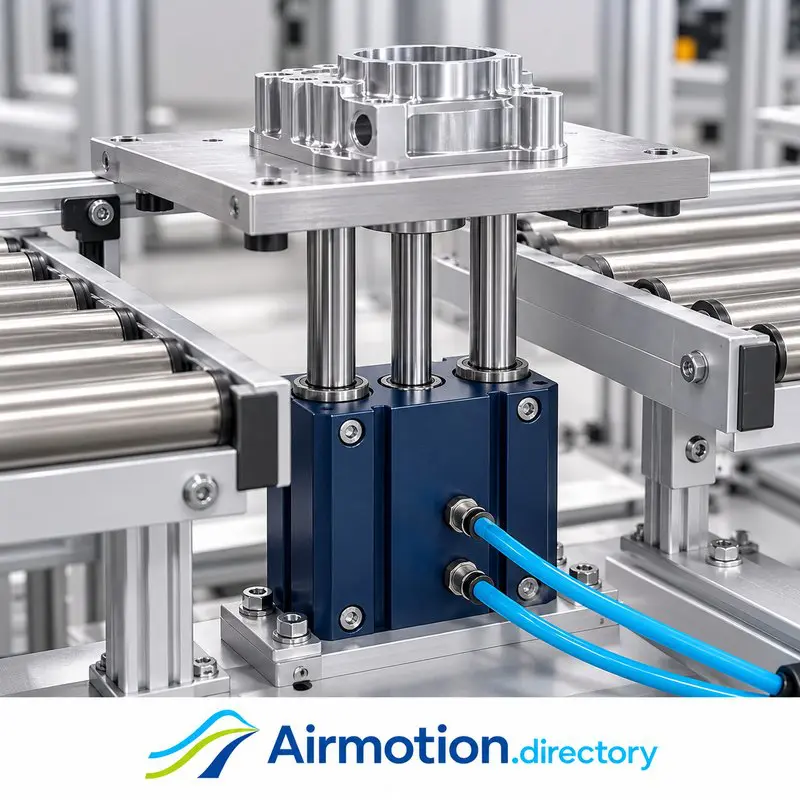
Lifting a work carrier
A carrier needs to rise above a conveyor for the next operation. A guided cylinder can support the lifting platform while resisting rotation. Include the platform, parts and any offset in the load calculation. Vertical applications also require the machine designer to address what happens if air pressure is lost.
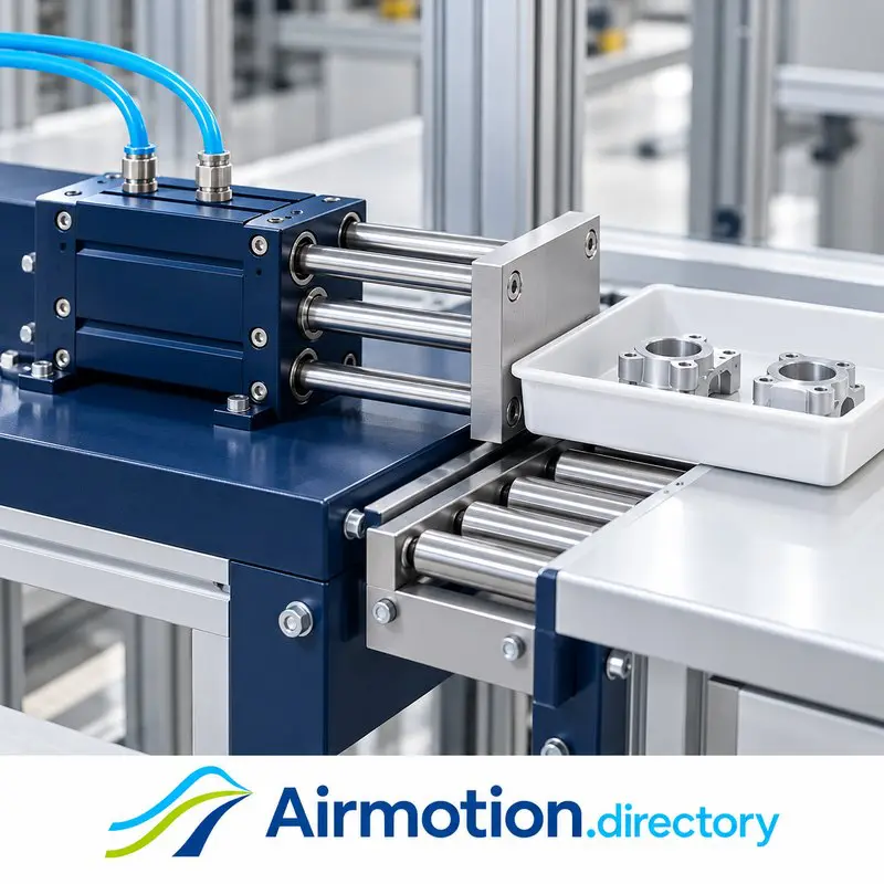
Transferring a tray
A broad pusher moves a tray from one conveyor section toward a receiving surface. The guide arrangement supports the pusher plate as the load acts away from the cylinder centerline. Stroke, tray resistance and the changing load position matter alongside the cylinder’s available thrust.
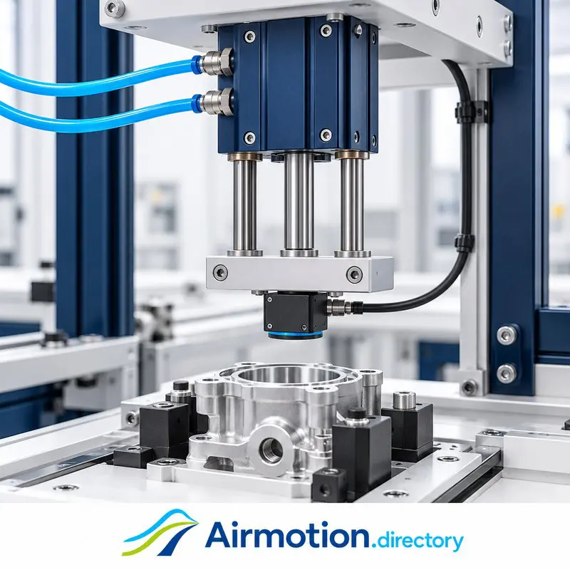
Positioning an inspection head
An inspection sensor moves toward a component held in a fixture. A guided actuator helps retain the sensor’s orientation during approach and withdrawal. Specify allowable movement and alignment at the sensor, then verify the selected actuator and mounting against those requirements.
Application images are illustrative examples, not photographs of the featured brands’ products or customer installations.
Three brands to know
These independent examples show different guided-cylinder arrangements. Inclusion does not imply that Airmotion Directory represents or supplies the featured brands.
PHD
PHD’s Series CTS guided compact pneumatic cylinders use guide shafts to prevent rotation and increase side-load capacity. Their short body suits applications where space is limited and guidance is required. Compare the selected configuration’s mounting, stroke and load data.
Mindman
Mindman’s MCGA twin-guided range includes stop/lift and push configurations. Its published application examples include handling work carriers and pushing across conveyor systems. Different variants provide different guide and bearing arrangements, so match the complete model to the duty.
CHELIC
CHELIC’s GHU range combines a pneumatic cylinder with an H-shaped twin-guide support. The guide arrangement resists torsion and lateral loads, with mounting and cushioning features described for the range. Check the selected bore, stroke and installation details rather than assuming all guided units are interchangeable.
What to compare before choosing
Load and turning moment. Include the moving plate, tooling and workpiece. Establish the center of gravity and distance from the guide support throughout the stroke. A light load mounted far from the guide can create a consequential turning moment.
Thrust and guide capacity. Check available cylinder force at the actual working pressure separately from the guide’s permitted loads and moments. Satisfying one rating does not establish that the other is adequate.
Stroke, speed and stopping. Define the required travel and cycle time. Compare the selected actuator’s limits and end-of-stroke cushioning or stopping provisions. Flow controls can adjust airflow, but do not establish the guide’s load capacity or a guaranteed positioning accuracy.
Alignment and mounting. Specify the permitted play, deflection and repeatability at the load. Check the bearing arrangement, mounting rigidity, available space and access to ports and sensors. Do not force a guided actuator to follow a misaligned external mechanism.
Installation conditions. Confirm air quality, temperature, contamination exposure and maintenance needs. For vertical motion, define the required response to pressure loss with the machine designer and supplier. Guidance alone is not a load-holding device.
What brought you here?
Exploring an application or purchase?
For one defined application question, explore Application IQ. For an actual purchase, quotation or supplier choice, see The Buyer’s Second Opinion.
Working on a customer opportunity?
For one active customer opportunity and its commercial approach, see The Seller’s Second Opinion.
Have a guided-cylinder requirement?
Share the task, moving mass, load position, stroke, mounting orientation, working pressure, cycle time and required alignment. Include a sketch showing the load’s distance from the actuator. For a replacement, provide the complete model number, quantity and destination country. Product inquiries are separate from the advisory services above.